Thursday, February 3, 2011

Color Sensor

This is the color sensor that was on the bread board with electical tape on it

This is the finished product with all the connections


This is the sensor part of the light and also ldr


This is my parners finshed line follower already attached to the robot

Tuesday, February 1, 2011

Using Square bot


Today we used the Square bots that we had built and used RobotC to program. Using Robot C is just like using a C based language. Using robot c is a lot more memory compared to the picaxe program wich is basic based.
Our first task was to run the robot though a maze so that it could navagate though the course only using distance that we inputed.

After seeing that it is very hard to only use distance and no sensors to run our robot professor mason put us in teams of two. in our teams we were given two quad encordrs to make it easer for the robot to manuaver.


after the event it is event that we need to use more sensors to make our robot more efficent.

Thursday, January 27, 2011

Wednesday, January 26, 2011


 This is a video of our little robot working with the demonstration of the LDR sensor.

 This is our connection from the brain to the motor control chip
This is our motor control chip which the red wire and black wire from the mouse will go inbetween the yellow wire

Thursday, January 20, 2011

Wednesday, January 19, 2011

1/19/11 Transistors

This is with our logic probe grounded. Note the led is off showign that there is no current even though our other led is still on showing that there is current though that part of the circuit.

Here we have the light working with out bligging in our probe. note how bright the led is.


This is just the back part showing our connections for the comonents.


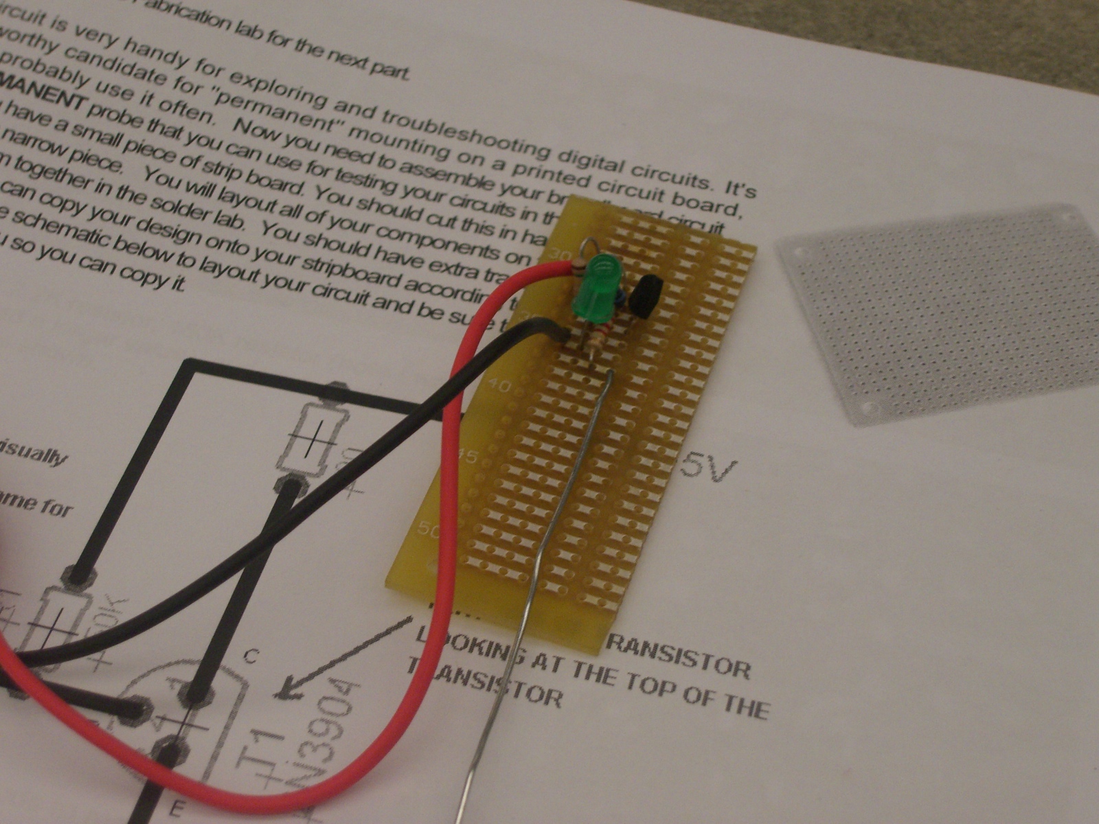
This is the final product of our test probe with all our parts intirgrated.

Here we are grounded and thus no current flows though the circuit.

Here we see tht when inserting the probe(green wire) we have the light bulb illuminate brightly when the amount current goes though the resistors.

This is the prototype for our logic probe that will test if there is connectivity between parts.

Here we are using a potnetimator (1M ohm) along with other reisisotrs to demonstrante the amount of current needed to light the light bulb.


This picture is very blurry but we can see that when the button is pushed the light goes on thus allowing current to flow though/

Here we are  demonstrating that when using a transistors (NPC) that the base takes in a low current to allow flow from though the circuit.

Thursday, January 13, 2011

January 12 2011

After building our ac power supplies for our breadboards, we were instructed to test if they had continuity . To do this Professor Mason handed us a Packet that demonstrated how to use a multimeter. After taking a crash course on how to use a multimeter we test what the voltage was reading from the power supply (which was 5.15V). Then we were instructed to build varies breadboards under certain conditions. The only frustrating part of this exercise was finding the right resistors. Many times i was forced to use a parallel connection to get the right resistance. Normally this would be an easy task since finding Equivalent resistance is a breeze, however finding the correct resistance from a supply that is very assorted can prove to be frustrating. After finding the correct components I was back on track and competed the three LED exercise by demonstrating if there is more resistance then you will get a dimmer light showing Ohms law of V=IR. After that professor mason showed a supply list of the LED's we had in our kits. He showed that not only does the light bulb need a certain amount of current to flow though it. but also it eats a certain amount of voltage from the power source. This is useful to know if one is going to build a circuit that will have the brightest light. In this exercise we had to demonstrate our knowledge in using Kirchhoff's laws and also Ohms laws to find what the correct resistor to use to achieve the brightest light.