Thursday, January 27, 2011
Wednesday, January 26, 2011


Thursday, January 20, 2011
Wednesday, January 19, 2011
1/19/11 Transistors
 This is with our logic probe grounded. Note the led is off showign that there is no current even though our other led is still on showing that there is current though that part of the circuit.
  Here we have the light working with out bligging in our probe. note how bright the led is.
 This is just the back part showing our connections for the comonents.
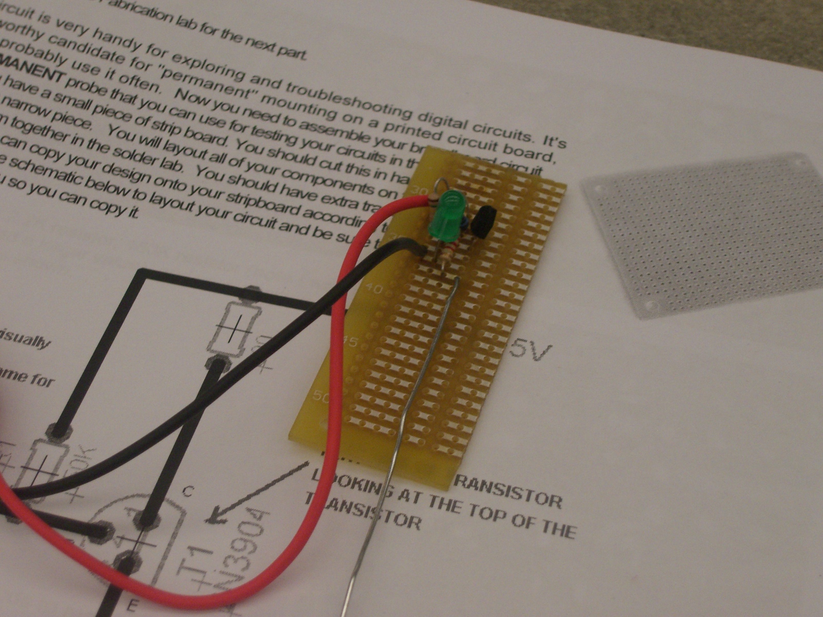
 This is the final product of our test probe with all our parts intirgrated.
 Here we are grounded and thus no current flows though the circuit.
  Here we see tht when inserting the probe(green wire) we have the light bulb illuminate brightly when the amount current goes though the resistors.
  This is the prototype for our logic probe that will test if there is connectivity between parts.
 Here we are using a potnetimator (1M ohm) along with other reisisotrs to demonstrante the amount of current needed to light the light bulb.
 This picture is very blurry but we can see that when the button is pushed the light goes on thus allowing current to flow though/
 Here we are demonstrating that when using a transistors (NPC) that the base takes in a low current to allow flow from though the circuit.
Thursday, January 13, 2011
January 12 2011
After building our ac power supplies for our breadboards, we were instructed to test if they had continuity . To do this Professor Mason handed us a Packet that demonstrated how to use a multimeter. After taking a crash course on how to use a multimeter we test what the voltage was reading from the power supply (which was 5.15V). Then we were instructed to build varies breadboards under certain conditions. The only frustrating part of this exercise was finding the right resistors. Many times i was forced to use a parallel connection to get the right resistance. Normally this would be an easy task since finding Equivalent resistance is a breeze, however finding the correct resistance from a supply that is very assorted can prove to be frustrating. After finding the correct components I was back on track and competed the three LED exercise by demonstrating if there is more resistance then you will get a dimmer light showing Ohms law of V=IR. After that professor mason showed a supply list of the LED's we had in our kits. He showed that not only does the light bulb need a certain amount of current to flow though it. but also it eats a certain amount of voltage from the power source. This is useful to know if one is going to build a circuit that will have the brightest light. In this exercise we had to demonstrate our knowledge in using Kirchhoff's laws and also Ohms laws to find what the correct resistor to use to achieve the brightest light.
Tuesday, January 11, 2011
January 11 2011 (first Meeting)
Today we in class we went over the labsafty manual which showed us what to do in case of an emergency. also it has many guied lines that go over why many of the rules are implimted for our safty. After the lecture of the safty manual we all took a quiz which showed we all understood the percautions, safty, and procdures during the labs. After we all watched a video which showed good and bad soddering jobs.
After we alll went to the faberication room and we went to work on soddering. first we were given compoents that we had to mount on a board. After we had to sodder many wires together showing that we are able to fabericate many wires together. after we were told to strip a power sources and fabericate it so we have pins running from the sources.
After we alll went to the faberication room and we went to work on soddering. first we were given compoents that we had to mount on a board. After we had to sodder many wires together showing that we are able to fabericate many wires together. after we were told to strip a power sources and fabericate it so we have pins running from the sources.
Subscribe to:
Comments (Atom)